
An inductor is basically a coil of wire, which might or might not be wrapped around a metal bar or rod, or some other cylindrical object. You often see inductors in a circuit as coils of what appear to be bare copper wire, wrapped around a cardboard or plastic core. The copper is not actually bare; it is coated with a thin enamel insulation, similar to enamel paint. The reason enamel-insulated wire is often used for inductors is because it is thinner and allows the coils to be placked tighter, and also because it tolerates higher temperatures than most PVC-based wire insulation. The most frequently seen enamels are either clear, or have a reddish tinge that makes the copper look especially gold or red in color. Unlike nearly every other basic electrical component, inductors can be home-made fairly easily, and electronic supply houses sell prefabricated cores of certain lengths, diamaters, and materials for wrapping copper coils around to make inductors.
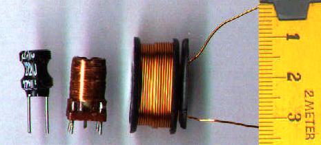
Inductors (image from Wikipedia Commons)
Inductors in DC Circuits
So what does an inductor do? The idea is simple: it fights any change in the current flowing through it. If a constant DC current is applied to an inductor, the inductor will, in theory, have little or no effect (the resistance of the wire may act like a low-value resistor). However, if anything causes the amount of current that is flowing to change, the inductor will fight that change. If the current tries to increase, the inductor will limit the rate at which the current can increase. Here's where it gets interesting: It will also limit the rate at which the current can decrease -- if the current tries to decrease, the inductor will actually "suck" current through in an attempt to keep it constant! The inductor does this by developing a voltage across it, from one end to the other, that tries to keep the current constant.
Here's a thought experiment. DO NOT ACTUALLY TRY THIS! Imagine a circuit with a battery connected to a switch and a large-value inductor, all in series. Initially, the switch is off, so no current is flowing. Then, we turn the switch on. What happens? The inductor does not allow the current to go to maximum immediately. Instead, the current ramps up gradually. Eventually, it reaches the maximum current that the battery is capable of supplying, but if we have a really large value inductor, it will take some number of seconds. If we had an ammeter or a scope with a current probe monitoring this, we could see it going up slowly at first, and then faster as it approaches the maximum value.

What happens when we turn the switch off? The current tries to go to zero immediately -- and the inductor doesn't like it one bit! It will develop a LARGE voltage in an attempt to "suck the current through", and very likely it will draw an arc across the switch contacts! This is why I said in the previous paragraph not to try this (unless you have a well-equipped lab and your fire insurance is paid up).
Inductors in AC Circuits
So in a DC circuit, an inductor can do drastic things when large step changes occur in the current, but as long as the current is in a steady state, nothing interesting happens; the current simply flows through. But what about an AC circuit? After all, a fundemental characteristic of AC is that the voltage, and hence the current, is changing all the time. Well, the obvious answer is that the inductor will resist all of the changes in the current, and it will do so in a manner that tends to keep the average current at a midpoint value. If we assume that the waveform is symmetrical, then the average current will be at the midpoint between the top and bottom peaks. If we further assume that the waveform has no DC offset, then that midpoint value is zero. Which means that, in effect, the inductor is acting like a resistor to the AC current.
At this point, we note something about AC. As we know from the Fourier theorem, all alternating signals are made up of sums of component sines. Let's consider two sine waves, both of the same peak-to-peak magnitude, but one of a low frequency and one of a higher frequency:

Low-frequency sine (green) and high frequency (red).
The dashed lines show the maximum slopes.
Note the slopes of the two sine waves where they cross the axis. You can see that the high-frequency one is rising and falling at a greater slope, and hence a faster rate, than the low-frequency one. So if we run both of them through an inductor, what happens? Per our discussion above, the inductor will resist both of them, but it will resist the higher-frequency one more. The inductor is acting like a frequency-dependent resistor, whose value increases with frequency -- which makes it a low-pass filter. You may recall seeing the previous sentence in the capacitors discussion. In fact, in an AC circuit, the inductor does the opposite of what the capacitor does; the capacitor is a high-pass filter; the inductor is a low-pass filter. And you can do, in theory, most of the same things with inductor-based filters that you can do with capacitor-based filters.
However, in reality, inductors are rarely used as filters in modern audio equipment. The reason is that small inductors are only effective in the RF range; an inductor-based filter for audio requires a huge inductor. There are practical problems with large inductors; besides the physical size, weight, and cost in copper, they also have the unfortunate habit of acting like radio antennas. A large inductor will pick up electromagnetic noise from other circuit components and the surrounding environment. (This is actually how a guitar pickup works. The magnet in the pickup sets up a field that is interfered with by the vibration of the guitar's strings. The pickup coil senses this interference and converts it into a signal. And as any guitar player who has played a guitar with non-humbucking pickups will tell you, the pickup coil also senses any other interference in the room and converts that into a signal too.) This is why you don't find many inductors in synths or other audio equipment.
Inductors, Electromagnets, and Applications
One other thing that an inductor does is create a magnetic field. This field is inside the coil and extends from one ends of the coil to the other, and slightly outside at each end. If you put an iron bar inside the coil, then when current is flowing, the bar becomes a magnet. This is precisely what an electromagnet is. If you mount the bar so it can slide in and out of the coil, then when current is flowing the magnetic field will pull the bar into the coil. If you then connect a spring to pull it back when the coil is not energized, you have a solenoid. If you connect a switch to the piece of iron, you have a relay. Relays are useful for allowing high voltage circuits to switch low-voltages ones on and off, or to allow DC circuits to switch AC circuits, or vice versa.
Transformers
If you run AC through the coil, you will obviously create an alternating magnetic field. One thing that an alternating magnetic field can do is induce a current into another coil that happens to be wound around the same core. This is precisely what a transformer is. A transformer is a power-converting device.
Recall that power, measured in watts, is calculated as:
watts = EI
where E is the voltage and I is the current. Now, in the transformer world, they don't use the term watts; they call them "volt-amps", or VA, instead. There's a reason for this that I won't get into; if you've ever heard the term "power factor", it has to do with that. The two coils of a transformer maintain a constant VA; VA in equals VA out. However, the voltage is not constant; it is determined by the ratio of the number of turns in the coils. If the primary coil (the one the power is applied to) has 100 turns, and the secondary coil (the one the current is being induced in) has 50 turns, the ratio is 2:1, and the voltage across the secondary coil will be half that applied to the primary coil. Since the VA is constant, that means the secondary coil will supply twice the current applied to the primary coil. That's how the power supply in a synth steps down the high mains voltage to the low voltages used by the synth circuitry. It's also how the output transformer in a tube amplifier converts the high-voltage signal from the output tube into the lower-voltage, higher-current signal needed to drive the loudspeaker. (And it should be noted that the loudspeaker itself contains an inductor, which creates the magnetic field that moves the speaker cone.)
Specifying Inductors and Transformers
The basic unit of inductance is the henry (no kidding), abbreviated H. As it turns out, one H is a larger amount of inductance than what is generally needed for the purposes for which inductors are used in electronics, so most inductors you will see in electronics parts catalogs will be specified in millihenries, or mH. Inductors will also be rated according to their maximum current capacity.
Transformers are rated in terms of the volt-amp (VA) capacity, and the turns ratio. There is usually also a maximum current rating (which is a function of how the transformer is constructed) and a maximum operating temperature. The turns ratio tells you what output voltage you can achieve for a given input voltage, and from that you can figure the maximum output current achievable, and compare to the transformer's maximum current rating. Transformers often have a multi-tapped coil on one or both sides; some of the taps allow some of the turns on that coil to be bypassed, which effectively changes the transformer's turns ratio. This is common in transformers intended to be used in power supplies; there will usually be taps on the primary side to accommodate both U.S. 120V mains and European 240V mains, and there may be a third one for Japanese 100V mains. If the device containing the power supply is taken to a different part of the world, it can be adapted to a new mains voltage by moving the power input lead to a different tap, or perhaps through a switch arrangement which accomplishes the same thing. Some transformers also have multiple taps on the secondary side, that allows the transformer to supply two or more secondary voltages in one unit. Remember that transformer depend on an alternating magnetic field being set up by the primary coil, and so they only work with AC voltages.
Summary
That's as far as I'm going to into this topic. There's a lot about inductors that I've ony hinted on, because the topics are more relevant to power engineering than they are to electronics. But if you are interested, do some Internet searches on the terms "reactance" and "power factor". As it turns out, when you get into these topics, you will discover that capacitance and inductance are two sides of the same coin, and there is some hairy but interesting math that arises.
No comments:
Post a Comment